
The Project:
- A silo belonging to a Midwest based grain marketing and processing conglomerate suffered a catastrophic failure on its first filling cycle after being retrofitted with a shutter type access door. AMG was approached with a request to investigate a series of other large welded steel grain silos or tanks in their system, all of which had recently been retrofitted with similar shutter type access doors.
- The vertical lift access doors illustrated in Figure 1 are used to permit material handling equipment such as skid steers and front-end loaders into the silos for cleaning and maintenance.
- The likely cause of the failure was determined by observational evidence and by analysis to be the high stress concentrations at the door's head-to-jamb intersections.
Constraints and Challenges:
There were several constraints:
- The solution required the continued use of the existing doors which were already bought, paid for, and installed, since they met all the operational and safety objectives of the client.
- The first constraint led to the second, which was that the solution had to involve reinforcing the silo shell to collect and pass the membrane stresses safely around the approximately 12 ft square door opening in the wall.
- The primary stresses involved were the vertical normal stresses, called meridional compression stress, and the horizontal tensile stresses, called hoop tension.
- The challenge was to come up with a solution and demonstrate its efficacy to the satisfaction of the client's in-house structural engineers, then prepare contract documents as quickly as possible so that the silos could be strengthened between the time they were emptied from the previous harvest and readied for receiving grain from the next harvest season.
- The remedial solution needed to be robust, practical and one that could be executed in the available time frame. Consequently, the capabilities of the locally available contractor labor pool and the ready availability of structural materials had to be considered.
The Solution:
- The approximate method used to start the design was to compute the area of shell lost by the door cut-out and provide that much replacement reinforcing distributed around the opening. This was followed by a Finite Element Analysis of a section of the shell with and without the added reinforcing.
- Included in the analysis were the meridional compressive forces from the roof and shell weight, the circumferential hoop tension forces from the grain pressure, and the meridional and radial grain pressure forces computed by the Janssen method.
- The Finite Element Analysis Model used to analyze the silo is shown in Figure 2.
- The original stressed condition around the door opening is shown in Figure 3.
- The proposed reinforcing around the door opening is shown in the model in Figure 4.
- The stressed condition around the door opening after reinforcing is shown in Figure 5.
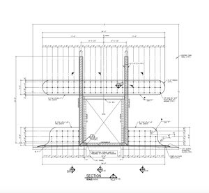
- A typical elevation from the contract drawings showing the reinforcing around the door opening is shown in Figure 6.
Software Tools That Were Used:
- Laser Scanning of each silo door location from inside and outside.
- MultiSTEEL for building a 3D Model from the laser point cloud scan.
- Navisworks® for moving around in the 3D image to visualize all aspects of the 3D Model.
- AutoCAD® to generate details for the contract drawings.
- pro to construct and analyze the 3D Finite Element Analysis (FEA) Model of the original silo door opening and the modified door opening.
Figure 1 – Typical Shutter Type Access Door in the Open Position.
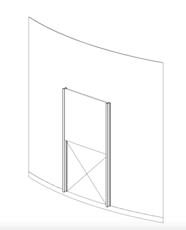 Note that when the door is in the closed position, it only resists the radial bursting pressure from the stored grain, it does not collect and carry the membrane stresses in the silo shell around the opening.
Figure 2 – Wire Frame of a Typical Grain Silo with Discharge Tunnel and Access Door Used for Finite Element Analysis (FEA)
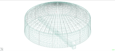
Note that while the access door is difficult to visualize, it is located immediately above the end of the discharge tunnel.
Figure 3 – Results of a Finite Element Analysis of the Unreinforced Silo Shell
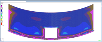 Note the two bright spots at the door head-to-jamb intersection. These represent concentrations of hoop tension stress which are 139% of the code prescribed allowable stress but 43% of the ultimate stress of the steel material. Consequently, the silo did not fail on first filling, but remedial action is required. Observation of salvaged parts of the failed silo indicated that the failure probably initiated at these locations. Because of its taller geometry, the silo that failed would have had higher stress levels than this silo.
Figure 4 – Representation of the Reinforcing Plates Added Around the Door Opening in the FEA Model.
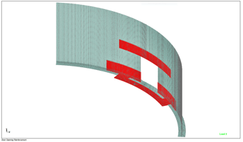 Note that the reinforcing plates on the silo wall above the door head and on the silo floor below the door sill collect hoop tension and transfer it above and below the door opening. There are also structural Jamb reinforcing elements which do not show in this representation.
Figure 5 – Results of a Finite Element Analysis of the Reinforced Silo Shell.
%2c%20No%20Captions.png?width=381&name=Figure%205%20-%20Option%20%233%20Plus%20-%20Hoop%20Tension%20(Sy)%2c%20No%20Captions.png) Note the different color of the spots at the door head-to-jamb intersection. These represent concentrations of hoop tension stress which are 29% of the code prescribed allowable stress.
Note the different color of the spots at the door head-to-jamb intersection. These represent concentrations of hoop tension stress which are 29% of the code prescribed allowable stress.
Figure 6 – Typical Interior Elevation View of the Reinforcing Around the Access Door Opening from the Contract Drawings.
Key Innovations & Approaches:
Like all engineering problems, the correct solution is always based on engineering fundamentals and theoretical principals. Turning those fundamentals and principals into a practical and cost-effective solution is where AMG’s expertise came into play. It takes the right know-how and experience to solve a difficult challenge such as these tanks presented.
About the Author:
 Tim McCrate is a Sr. Structural Engineer at AMG. He has been with the company for 27 years. Tim received a bachelor's degree from the University of Dayton in Civil Engineering and a master's degree from the University of Missouri in Structural Engineering.