The Project:
- A European based building materials manufacturing conglomerate intended to build a greenfield plant in central Missouri to manufacture asphalt roofing shingles.
- The European conglomerate contracted with a Mexican based storage silo fabricator for the material handling conveyors and storage silos on a design-build basis. The silos were to store aggregate to be applied to the top and bottom surfaces of the shingles.
- The Mexican contractor approached AMG, which is licensed in 30 states, to help with the structural design and seal the drawings.
- The structural components consisted of the following:
-
-
- The 200 ft long, 3-span belt conveyor bridge with cantilevered catwalk.
- The 30 ft tall platform structure supporting (28) 12 ft Diameter x 50 ft tall, silos designed to hold 500,000 pounds of aggregate each, 14 million pounds in total (the seismic demand controlled the lateral load design due its proximity to the New Madrid seismic zone).
- The (28) skirt supported silos with hopper bottoms and corbels for supporting the head house.
- The tripper belt conveyor bridge inside the headhouse.
- The headhouse structure.
- The exterior access stair.
- The 400 ft long, 4-span, covered, twin gallery conveyor bridge with (3) catwalks. The vertical alignment of the trusses in one span have a convex break while those in another span have a concave break.
- Three belt conveyor tensioning weight access platforms.
-
Constraints and Challenges:
There were many constraints and challenges.
- A compressed time frame of 12 weeks from kickoff to permit drawings submittal to meet a contractual milestone.
- AMG’s original scope was to review and approve the design by a Mexican consulting firm, but it evolved into doing the design at the request of the Mexican design-build contractor in order to meet the contractual deadline.
- All structural steel was to be hot dip galvanized, but the dip tank was 1m x 1m x 10m, which limited the piece size and sub-assembly size.
- AMG’s project engineer spent a week at the office of the Mexican design-build contractor developing details. Given the connection detail designs, the 3-D CAD modelers the Mexican design-build contractor used for shop drawing preparation were able to prepare good quality shop drawings even though they were not experienced structural steel detailers.
- Given the time constraints, AMG had to sacrifice exploring multiple solutions for steel economy and go with the mutually agreed upon solutions from the kick-off meeting to make the deadline and achieve the mandatory level of accuracy required.
The Solution:
The complexity of supporting the headhouse and the tripper conveyor truss on the moving silo roofs was the most challenging.
Figure 1 – shows a sketch depicting the ½” variable, reciprocating lateral movements of the roofs of the (28) silos due to the 1/8” vertical deflections of the supporting trusses caused by filling and emptying of the 2,000,000 pounds of aggregate in the (4) silos supported within a bay.
Figure 2 – shows the innovative column base anchorage detail that was used to eliminate the need to coordinate (20) shear lugs with the foundation design engineer. The two 2” Diam high strength threaded rods are sleeved through the 3 ft thick pile-supported mat foundation and post-tensioned to create a constant normal force to generate shear-friction and strong axis bending moment.
Figure 3 – shows one of the mid-bay joints where truss framing from 8 directions intersects. The trusses support four silos or a total of 2,000,000 pounds.
Figure 4 – shows a headhouse support on a silo corbal. It uses UHMW Polyethylene bearing pads and rollers to resist gravity, lateral, and uplift loads while permitting longitudinal translation and horizontal rotation.
Figure 5 – shows the headhouse extension beyond the silos which is supported by unbraced columns to permit relative horizontal movements between the ground and headhouse. The columns are located under the intersection of the supply conveyor bridge and the tripper conveyor bridge while the headhouse cantilevers in two directions.
Figure 6 – shows the tripper conveyor bridge which is designed to maintain a straight line while the headhouse floor on which it rests moves alternately back and forth beneath it.
Figure 7 – shows the 80 ft tall headhouse access stair which is designed to move with the headhouse while the base is fixed.
Figure 8 – shows the erected silo platform support structure, the 28 silos, and the headhouse frame before the cladding was installed.
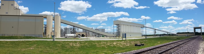
Figure 9 – shows a panoramic view of the total project.
Software Tools That Were Used:
- Auto CAD was used by the Mexican design-build contractor to generate plans and elevations.
- STAAD Pro was used by AMG to model the 28 ft x 252 ft x 30 ft tall silo support structure.
- Details were hand sketched.
- Shop drawings were prepared by the Mexican design-build contractor using SOLIDWORKS TM.
Figure 1 – Plan at headhouse floor showing repeated motion of silo roofs due to aggregate loading and unloading.
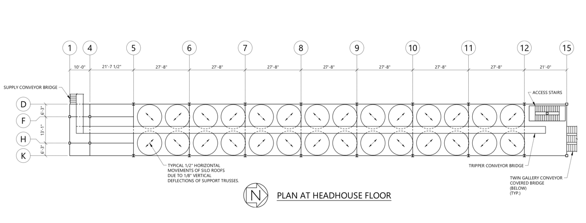
Figure 2 – Column Base connection showing post-tensioned anchor bolts using shear friction in lieu of shear keys for transverse moment frames and embedded gusset plate for longitudinal braced frame shear transfer.
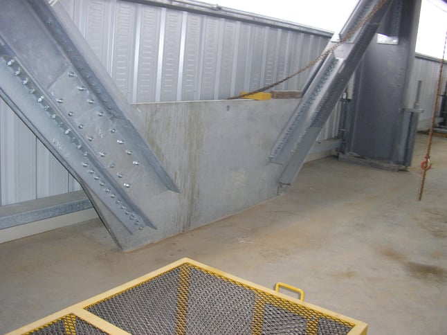
Figure 3 – Photograph showing (8) sided truss connection at mid-bay supporting four 500,000 pounds silos.
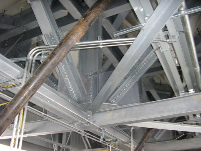
Figure 4 – Photograph showing Headhouse supported by UHMW Polyethylene pads and Rollers to permit silo movements while providing headhouse support reactions. One pad for gravity load, two vertical rollers for lateral load and one horizontal roller for uplift load. The three acting together permit longitudinal translation and horizontal rotation. (Note that one of the two vertical rollers is obscured behind the support beam).
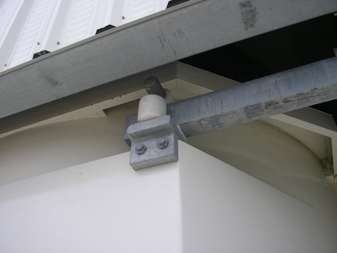
Figure 5 – Photograph showing Headhouse extension beyond silos which is tied to silos with a horizontal truss for lateral stability while supported by unbraced HSS columns for gravity and uplift. This permits lateral movement of headhouse relative to the ground.
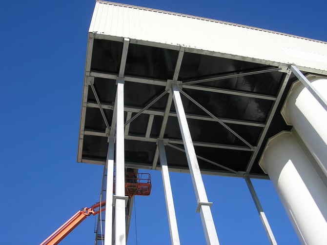
Figure 6 – Photograph taken inside of headhouse showing the tripper conveyor carried on a truss bridge that is supported on each bent at 28 ft for gravity load but spans 200 ft horizontally to maintain the alignment of the conveyor. Each piece of floor plate covering the interstice is tied to only one silo to permit differential movement.
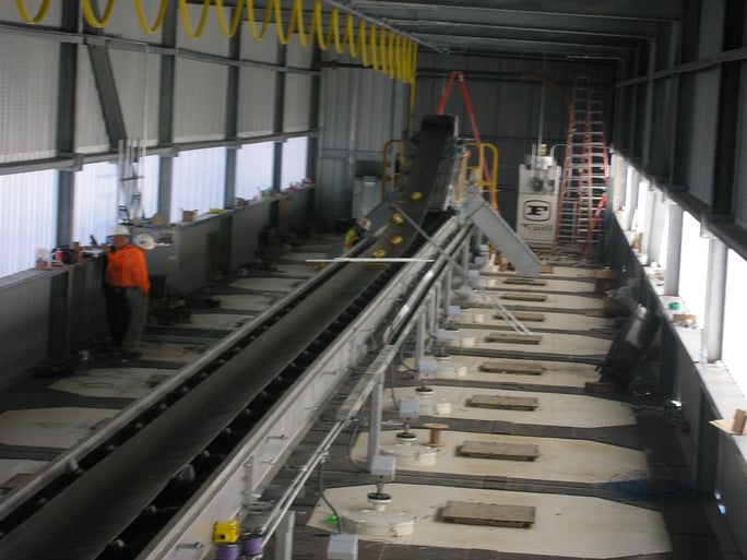
Figure 7 – Photograph showing headhouse access stair supported by a single HSS center post so that the top and mid landing can move relative to the base with the lateral movements of the headhouse.
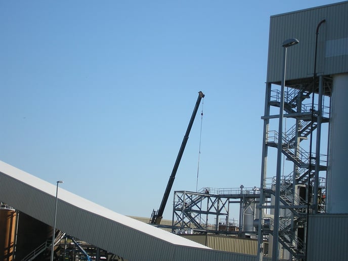
Figure 8 – Photograph shows the silo support platform, silos, headhouse, stairs, the tripper on its bridge, and parts of the supply conveyor bridge and the twin gallery conveyor bridge.
%20(002).jpg?width=695&name=Figure%208%20-SAM_0675%20(002)%20(002).jpg)
Figure 9 – Photograph showing Panoramic View of full project a) 200 ft supply conveyor bridge, b) 28 silo storage structure with headhouse, c) 400 ft enclosed, twin gallery conveyor bridge.